5G V2X with NR sidelink
Physical layer structure
Sidelink
bandwidth part (BWP) is defined to support the flexible numerologies in
operating on various spectrum band such as the intelligent transport system
(ITS) dedicated band and the licensed band of frequency range 1 (FR1) and FR2.
For sidelink synchronization, GNSS, gNB/eNB and the NR sidelink UE can be used
as a synchronization reference source of a UE.
The NR
V2X sidelink uses the following physical channels and signals:
- Physical sidelink broadcast channel (PSBCH)
and its de-modulation reference signal (DMRS)
- Physical sidelink control channel (PSCCH)
and its DMRS
- Physical sidelink shared channel (PSSCH) and
its DMRS
- Physical sidelink feedback channel (PSFCH)
- Sidelink primary and secondary synchronization
signals (S-PSS and S-SSS)
- Phase-tracking reference signal (PT-RS) in
FR2
- Channel state information reference signal
(CSI-RS)
Sidelink
control information (SCI) in NR V2X is transmitted in two stages. The
first-stage SCI is carried on PSCCH and contains information to enable sensing
operations, as well as information about the resource allocation of the PSSCH.
PSSCH transmits the second-stage SCI and the sidelink shared channel (SL-SCH)
transport channel. The second-stage SCI carries information needed to identify
and decode the associated SL-SCH, as well as control for hybrid automatic
repeat request (HARQ) procedures, and triggers for channel state information
(CSI) feedback, etc. SL-SCH carries the transport block (TB) of data for transmission
over SL.
PSCCH
and PSSCH are multiplexed in time and frequency within a slot for short latency
and high reliability. DRMS is frequency multiplexed with PSCCH or PSSCH in the
corresponding DMRS symbols. PSFCH, which is used for sidelink HARQ feedback for
unicast and groupcast, is transmitted at the end of a slot, which is preceded
by an additional guard symbol and an automatic gain control (AGC) symbol. Two
multiplexing examples are shown in Figure 1(a) and 1(b).
 |
Resource allocation
There
are two resource allocation modes: mode 1 and mode 2. Mode 1 for resource
allocation by gNB and Mode 2 for UE autonomous resource selection are very
similar to Mode 3 and Mode 4 in LTE sidelink respectively. For mode 1, gNB
schedules to UE the dynamic grant resources by downlink control information
(DCI), or the configured grant resource type 1 and type 2 by radio resource
control (RRC) signalling and DCI respectively.
In Mode
2, the sensing operation to determine transmission resources by UE comprises 1)
sensing within a sensing window, 2) exclusion of the resources reserved by
other UEs, and 3) select the final resources within a selection window. In Mode
2, shortly before transmitting in a reserved resource, a sensing UE
re-evaluates the set of resources to check whether its intended transmission is
still suitable, considering a possible aperiodic transmission after the
resource reservation. If the reserved resources would not be part of the set
for selection at this time, then new resources are selected from the updated
resource selection window. In addition to the re-evaluation, pre-emption is also
introduced such that a UE selects new resources even after it announces the
resource reservation when it observes resource collision with a higher priority
transmission from another UE.
Sidelink HARQ feedback, sidelink CSI and PC5-RRC for unicast and groupcast
NR
sidelink supports sidelink HARQ-ACK for sidelink unicast and groupcast services
for improved reliability. Two sidelink HARQ feedback operations are defined,
HARQ-ACK with ACK and NACK, and HARQ-ACK with NACK only. When ACK/NACK
operation is used, the sidelink HARQ-ACK procedure is similar to that of Uu for
non-codeblock group feedback, i.e. the HARQ-ACKis transmitted based on the
success or failure of the whole transport block. NACK-only operation is defined
for groupcast to allow a a larger number of Rx UEs to share a single PSFCH
resource by sending feedback only when a Rx UE receives SCI but fails to decode
the transport block. The transmission of NACK-only feedback can be restricted
to UEs within given a radius, and any UE beyond it does not provide any
HARQ-ACK. This minimum range requirement of a service is provided together with
the associated QoS parameters from service layers. For mode 1, sidelink
HARQ-ACK information is reported to gNB to indicate whether additional
retransmission resources are required or not.
In
sidelink unicast transmission, Tx UE can configure aperiodic sidelink CSI
reporting from the Rx UE to get information it can use for sidelink link
adaptation and rank adaptation. CQI and RI are reported via MAC layer
signalling, in a PSSCH transmission for this purpose. In addition, radio link
monitoring is adopted to manage a sidelink connection.
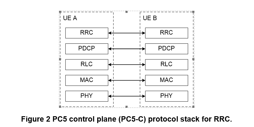
To
support exchange of the AS layer configuration and UE capability information
between UEs, PC5-RRC is defined for unicast sidelink communication. The AS
protocol stacks of the control plane for RRC is depicted in Figure 2.
Cross-RAT and in-device coexistence between LTE V2X and NR V2X sidelinks
Depending
on the NR V2X and LTE V2X deployment, it is envisaged that an optional UE
design can be supported where a device has both an LTE-V2X RAT and an NR-V2X
RAT which are able to inter-communicate. 5G V2X defines two Cross-RAT
operations. LTE Uu can control NR resource allocation mode 1 by providing
configured grant Type 1 configurations via LTE RRC signalling, and resource
allocation mode 2 by LTE Uu RRC providing the semi-static configurations
relevant to resource pools, sensing, etc. NR Uu can control LTE resource
allocation mode 3 by transmitting an NR DCI which contains the information
needed to dynamically control the LTE sidelink, and resource allocation mode 4
by NR Uu RRC providing the necessary semi-static configurations within which
the LTE-V2X RAT autonomously selects resources for sidelink transmission.
It is
envisaged that there will exist devices that support both LTE-V2X and NR-V2X,
and which will be operating in both systems concurrently. If the two RATs are
widely spaced in frequency, e.g. being in different bands, then there need be
no particular issues to consider since it is assumed that a separate RF chain
will be provided for each band. If, however, a sufficiently close frequency
spacing is deployed, then it is desirable to enable a single RF chain to be
used in the implementation. In this case, the simultaneous transmission on both
RATs is prevented by the UE's single power budget, and one RAT cannot be
received/transmitted while the other RAT is doing the opposite. In this case,
one of the RATs may be dropped at times when both occur simultaneously, but
that in some cases where the priority of the V2X service on both RATs is known,
the higher priority one is automatically selected.